| DE / INT: | +49 - (0)36453 - 744-0 | US: | +1 707 4810216 |
| info@layertec.de | ussales@layertec.com |
Dielectric Coatings
The purpose of optical coatings is to change the reflectivity of optical surfaces. According to the materials and physical phenomena which are used one can in principle distinguish metallic and dielectric coatings. Metallic coatings are used for reflectors and neutral density filters. The reflectivity which can be achieved is given by the properties of the metal. Some of the most common metals for optical applications are described in our catalog.
Dielectric coatings use, however, optical interference to change the reflectivity of the coated surfaces. Another major difference is that the materials used for this kind of coatings show very low absorption. Using optical interference coatings the reflectivity of optical surfaces can be varied from nearly zero (anti reflection coatings) to nearly 100% (low loss mirrors with R > 99.999%). However, these reflectivity values are achieved only for a certain wavelength or wavelength range.

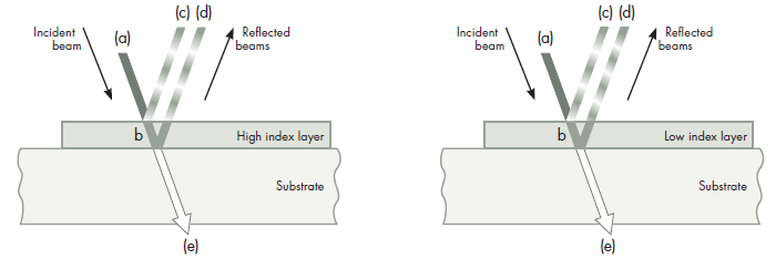
The influence of a single dielectric layer on the reflectivity of a surface is schematically shown in figure 1. An incident beam (a) is split into a transmitted beam (b) and a reflected beam (c) at the air-layer interface. The transmitted beam (b) is again split into a reflected beam (d) and a transmitted beam (e). The reflected beams (c) and (d) can interfere.
In figure 1 the wavelength is represented by the shading of the reflected beams. The distance from “light-to light” or “dark-to-dark” is the wavelength. Depending on the phase difference between the reflected beams constructive or destructive interference may occur.
The reflectivity of the interface between two media depends on the refractive indices of the media, the angle of incidence and the polarization of the light. In general, it is described by the Fresnel equations.
The phase difference between the beams (c) and (d) is given by the optical thickness n·t of the layer (the product of the refractive index n and the geometrical thickness t). Moreover, one must take into account that a phase jump of π, i.e. one half wave, occurs if light coming from a low index medium is reflected at the interface to a high index medium.

A single low index layer can be used as a simple AR coating. The most common material for this purpose is magnesium fluoride with a refractive index n=1.38 in the VIS an NIR. This material reduces the reflectivity per surface to R∼1.8% for fused silica and to nearly zero for sapphire.
Single wavelength AR coatings consisting of 2–3 layers can be designed for all substrate materials to reduce the reflectivity for the given wavelength to nearly zero. These coatings are especially used in laser physics. AR coatings for several wavelengths or for broad wavelength ranges are also possible and consist of 4–10 layers.

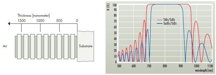
The most common mirror design is the so called quarterwave stack, i.e. a stack of alternating high and low index layers with an equal optical thickness of n·t = λ/4 for the desired wavelength. This results in constructive interference of the reflected beams arising at each interface between the layers. The spectral width of the reflection band and the achievable reflectivity for a given number of layer pairs depends on the ratio of the refractive indices of the layer materials. A large refractive index ratio results in a broad reflection band while a narrow reflection band can be produced using materials with a low refractive index ratio.
To visualize the effect of different refractive index ratios figure 3b compares the reflectivity spectra of quarterwave stacks consisting of 15 pairs of Ta2O5/SiO2 and TiO2/SiO2 for 800nm (n1/n2=2.1/1.46 and 2.35/1.46, respectively).
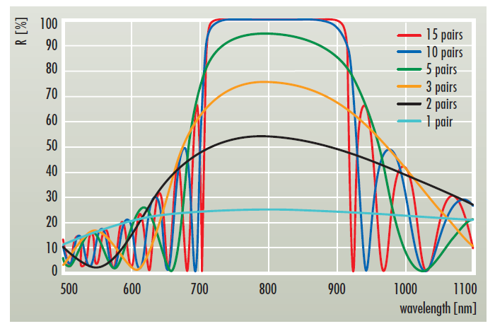
Assuming ideal coatings with zero absorption and scattering losses the theoretical reflectivity will approach R=100% with increasing number of layer pairs. Also partial reflectors with several discrete reflectivity values between R=0% and R=100% can be manufactured using only a small number of layer pairs (see figure 4). Adding some non-quarterwave layers to such a stack allows to optimize the reflectivity to any desired value.

Figure 4 also shows that an increasing number of layer pairs results in steeper edges of the reflectivity band. This is especially important for edge filters, i.e. mirrors with smoothed side bands. Extremely steep edges require a large number of layer pairs which in turn results also in a very high reflectivity. Extremely high reflectivity values require very low optical losses. This can be achieved by using sputtering techniques.
